One of the key value propositions for additive manufacturing is to create mechanically superior parts using complex geometric structures, such as the gyroid shown below. While complexity may be “free” from a processing point of view, taking advantage of this complexity in a useful way requires both sophisticated knowledge of the mechanical behavior of the selected material and expertise in modeling non-linear materials and structures. This case study highlights what is involved in simulating a complex additively manufactured structure. We have chosen SLS polyamide 11 (PA11) as the material, but the considerations are the same regardless of process/material combination.

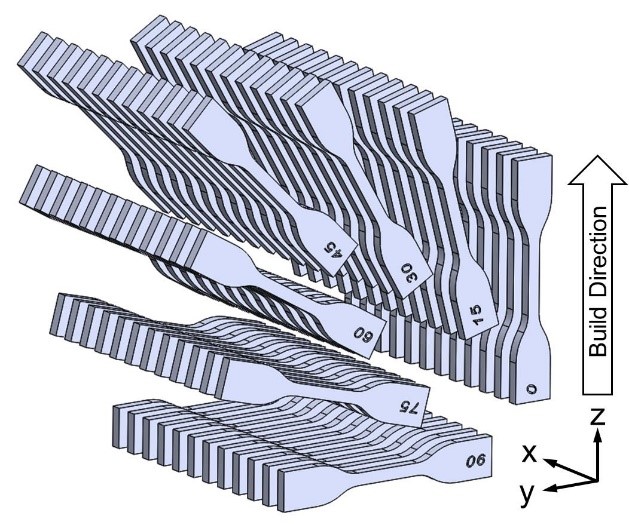
To begin, accurate mechanical analysis requires knowing the stress-strain response of the material under the relevant loading conditions. Mechanical properties listed on data sheets are useful for comparative purposes but are not sufficient for simulation-based design. To get the experimental data needed for an accurate model, we conducted a series of experiments to characterize the influence of loading mode (tension/compression), build orientation (θ), and strain rate (ἑ), on the mechanical behavior of SLS PA11.
The experimental data is shown in the figure below up to engineering strains of ±20%. We measured the orientation-dependent tensile response and found the elastic and yielding behavior to be effectively isotropic. From a design point of view, this greatly simplifies things because many additively-manufactured polymers exhibit anisotropic yield properties which must be subsequently modeled. We also measured the compressive stress-strain response at three strain rates to characterize the rate sensitivity of the material. The PA11 exhibited moderate rate dependence and asymmetry in the yield point between tension and compression.

To model the deformation of this material, we chose the three-network model from the PolyUMod® library of advanced user materials (www.polyumod.com), which was developed specifically for thermoplastics. The model was calibrated to the experimental data using MCalibration®. The figure below shows the calibrated material model plotted as heavy dashed lines. The model accurately captures the measured stress-strain behavior, including the rate-dependence and the difference in yielding between tension and compression.

Finally, using the calibrated three-network model for PA11, we simulated the deformation of the gyroid shown above using finite element analysis (FEA). The 3D mesh required for the FEA was generated using a custom meshing tool developed at Veryst Engineering. A snapshot of the simulation is shown below with the contours representing the magnitude of the von Mises stress that develops in the structure under uniaxial strain.

The predicted stress-strain response of the structure under uniaxial strain is shown below. Note the asymmetry in the non-linear regions. In tension, the structure is predicted to harden after yielding, whereas in compression, the stress is predicted to plateau until self-contact starts to occur.

In summary, advances in AM processing, simulation, and design will continue to enable the fabrication of increasingly complex end-use parts. Strategic mechanical testing, state-of-the-art material modeling, and non-linear FEA are all critical to enabling these advances.